Writing your first emulator Part I
I decided to make these posts to walk you through the process of creating a simple emulator for a simple processor: 1970 Caxton C. Foster’s Blue. Think of this tutorial as a way to give you ideas on how to write an emulator, when I started writing this I knew emulators existed and I was familiar with programming, but I just didn’t know where to begin. So if you feel like how I felt, I hope this post can help you and make things more clear.
We’re going to code an emulator in C++, but the approach used here can be applied to any language, some familiarity with computer architecture concepts and of course programming may be needed to follow this post.
Blue’s architecture
Blue is a simple and underpowered machine, but it still reflects the core concept of how computers work. In order to write something that will ressemble the original hardware, we first need to know the innards of the design.
These are the specs:
- 4096 words of addressed core storage of 16 bits per word.
- Words in data storage as treated as 15-bit integers plus sign.
- Instructions are 4 bit OP code with 12 bit address (4096).
- 16-bit Acc.
- 16-bit instruction register.
- 12-bit program counter.
- 12-bit Memory Address Register, 16-bit Memory Buffer Register and a 16-bit Z register that are not accessible to the programmer.
- 16 different instructions for the 4-bit OPCode.
- Two’s complement interpretation.
And here’s the instruction set:
- Octal representation for Op code
- 00-HLT XXXX: The computer will halt. The START button on the console will cause the computer to start going again, beginning with the instruction following the HLT.
- 01-ADD XXXX: The contents of XXXX are added tot the contents of the accumulator and the sum is put into the accumulator. If the result is greater than 2^15-1 or less than -2^15 the machine stops.
- 02-XOR XXXX: Exclusive OR of the contents of XXXX and Acc replace Acc.
- 03-AND XXXX: AND between address and Acc, replace Acc.
- 04-IOR XXXX: OR
- 05-NOT XXXX: Acc is inverted
- 06-LDA XXXX: Loads addresss into the Acc.
- 07-STA XXXX: Acc is copied to Address. Acc remains unchanged.
- 10-SRJ XXXX: Contents of program counter(present instruction location plus one) are ORed into 12 Acc bits. XXXX is copied into the program counter, used to jump.
- 11-JMA XXXX: If the sign bit of the Acc is one, the number XXXX is placed in the program counter. Else, does nothing.
- 12-JMP XXXX: Jumps to address XXXX
- 13-INP XXYY: Upper 8 bits of the Acc are cleared and the next 8-bit character from input device YY is entered into the low end of Acc. The XX part of the field is ignored. Blocks until transfer is complete.
- 14-OUT XXYY: The upper 8 bits of the Acc are sent to output device YY. The XX is ignored. Blocks until the device accepts data.
- 15-RAL XXXX: Acc is rotated left one place.
- 16-CSA XXXX: The number set into the console switch register replaces the contents of the accumulator.
- 17-NOP XXXX: Does nothing.
Now, the real implementation innards are kinda complicated, we have tons of logic gates and buses inside Blue, you can check this repo for more details. This makes the task of writing a hardware emulator much more complicated than writing a software emulator, at least a software emulator that only cares about interpreting programs and outputs. You can read about my attempt of a failed hardware emulator here.
For this exercise, we don’t really care about implementing all the buses and gate logic, we’re only worried about handling the registers properly and following what the specification tells us about how each instruction is interpreted.
Emulating our first cycle
Let’s start with the simple stuff. We’ll forget about any input/output handling and start by coding the core of our emulator, the function that will emulate the instruction cycle. That is, covering the steps that will be needed to process a whole instruction. We’ll begin by emulating the FETCH cycle.
Each cycle is made of 8 smaller steps, each step’s timing is defined by a clock and 8 lines that represent each of the steps. Every time Blue’s clock ticks, a line is set to HIGH and the others to LOW, this can be easily represented by a counter variable that increments from 1 to 8 and then it’s reset back to 1.
So, our emulated cycle will look as follows:
uint8_t clock_pulse = 1;

void emulateCycle()
{
	while (clock_pulse < 9)
	{
		process_tick(clock_pulse);
		clock_pulse++;
	}
	clock_pulse = 1;
}
As you can see a major cycle will consist of a loop of 8 smaller steps, each iteration we’ll call process_tick to execute any step defined by our instruction. Each instruction does different things at each step of the cycle and both cycles are made of 8 steps, so we can leave all the implementation details of FETCH/EXECUTE to this process_tick function.

Now, let’s start fleshing out some of the instructions. These are the common steps that we need to emulate for any instruction as long as the fetch cycle is active. Some instructions only need this cycle, while others need more steps and thus require an additional EXECUTE cycle. To achieve this, first we have to define some registers. All the registers are 16-bit wide, so uint16_t can be used as the type.
These are all the registers and RAM we’ll ever need for this implementation:
#define RAM_LENGTH 4096
uint16_t RAM[RAM_LENGTH];

typedef uint16_t blue_register;
blue_register A;         // Accumulator - For arithmetics, calculations
blue_register DIL;       // Data-In - To receive input data
blue_register DOL;       // Data-Out - To output data
blue_register DSL;       // Device Selector - To select IO device
blue_register IR;        // Instruction Register - Stores the current instruction and it's operands
blue_register MAR;       // Memory Address Register - Tells us which RAM address to read
blue_register MBR;       // Memory Buffer Register - Actual RAM contents as pointed by MAR
blue_register PC = 0x00; // Program Counter - To perform jumps and handle instruction numbers
blue_register SR;        // Console Switch Register - To input data manually
blue_register Z;         // Z register - Auxiliary register for calculations
I went a bit too fancy with the typedef instead of using plain uint16_t, but that’s totally optional. I just thought it would be more readable that way.
Inside process_tick we’ll code the logic for executing the common steps for FETCH cycles. So we also need to define the states and a variable to hold the current state.
typedef enum {
	EXECUTE,
	FETCH,
} State;

State STATE = FETCH;
Now let’s code the common steps.
void process_tick(uint8_t tick)
{
	switch (tick) {
	case 1:
		break;
	case 2:
		if (STATE == FETCH)
			PC += 1;
		break;
	case 3:
		if (STATE == FETCH)
			MBR = 0x00;
		break;
	case 4:
		if (STATE == FETCH) {
			IR = 0x00;
			MBR = RAM[MAR]; // The Clear in step 4 also means updating MBR in the next step
		}
		break;
	case 5:
		if (STATE == FETCH)
			IR = MBR;
		break;
	case 6:
		break;
	case 7:
		break;
	case 8:
		break;
	default:
		break;
	}
}
You’ll notice that we’re missing the part where the Memory Address Register is updated based on the Program Counter, without this, we’re stuck executing the same instruction again and again. However, this is a instruction-specific operation, so we need to start implementing the actual instructions if we want to advance through our program.
Emulating the NOP instruction
Let’s implement the easiest instruction first, the NOP instruction.

According to the spec, the NOP instruction does nothing when executed, so we only need to care about updating the MAR with the contents of the Program Counter so that the next instruction is executed after we’re done with NOP. This is the code we’ll need:
void do_NOP(uint8_t tick)
{
	if (tick == 8)
		MAR = PC;
}
Basically, if we’re at step 8, we’ll just update the MAR. Now let’s attach it to our process_tick function. First we define a function to help us know the number of the instruction we’re processing. For example, NOP is instruction number 15 in decimal, 0F in hexadecimal or 17 in octal.
uint8_t get_instruction()
{
	return ((IR & 0xF000) >> 12);
}
Now let’s use it in an if statement to execute our instruction. To do so, we’ll modify process_tick as follows:
void process_tick(uint8_t tick)
{
	...

	case 7:
		break;
	default:
		break;
	}
	uint8_t INS = get_instruction();
	if (INS == 15) {
		do_NOP(tick);
	}
}
There are better, more maintainable ways of doing this other than a bunch of if/else statements for every instruction. We’ll see that in the next post once we start introducing more instructions, or you can just take a peek at the emulator’s repo ;).
Now, let’s code the “infrastructure” we need to load a program and run it inside our emulator! Time to see the matrix! Our test program will be just a bunch of NOP instructions with random operands as you can clearly see. What we’ll use a test program is basically just machine code, we’re writing the instructions by hand using hexadecimal numbers. There’s an opportunity to create an assembler program that lets us write in “assembly” instead of plain numbers, but we’ll cover that later.

NOP takes no operands so their presence shouldn’t really affect the instruction, they’ll simply be ignored. The test program:
// The first nibble of the most significant byte holds the
// instruction. The rest is just operands.
// F0 03 means NOP with a 3 as an operand
// 17 00 03 in Octal

// Sample program
uint16_t program0[4] = {
	0xF000, // NOP 000
	0xF003, // NOP 003
	0xF000, // NOP 000
	0xF005  // NOP 005
};
We now need a way to load the program into the RAM and actually execute it. This will run our program in an infinite loop and give us debug information about the registers on every cycle:
void dumpRegisters()
{
	printf("PC: %04x A: %04x IR: %04x Z: %04x MAR: %04x MBR: %04x DSL: %02x DIL: %02x DOL: %02x\n", PC, A, IR, Z, MAR, MBR, (DSL & 0x00FF), (DIL & 0x00FF), (DOL & 0x00FF));
}

void runProgram(const uint16_t* program)
{
	std::cout << "Copying program to the RAM\n";
	memset(RAM, 0x00, RAM_LENGTH * sizeof(uint16_t));
	memmove(RAM, program, (RAM_LENGTH * sizeof(uint16_t)));
	for (;;) {
		emulateCycle();
		dumpRegisters();
	}
}

int main(int argc, char* argv[])
{
	runProgram(program0);
	return 0;
}
We can do all sort of quality of life additions at this point, for example, in the original repo I coded some sort of gdb replica to step instruction by instruction without needing to actually debug the emulator. But I guess I’ll leave this for later once the instructions start to get more complicated.
Time to see our emulator in action. Compile it with g++ or any C++ compiler you have available and run the executable!
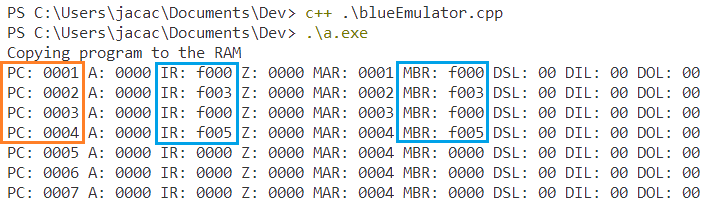
Even though this doesn’t look too impressive, it’s exciting enough! From the output you can see how the contents of the Memory Buffer Register, Instruction Register, Memory Address Register and Program Counter change with each cycle. Although the NOP instruction does nothing, we can be sure that the instructions are being read from the RAM and the PC has an effect on the MAR.
Emulating the JMP instruction
To spice things up let’s implement the JMP instruction.
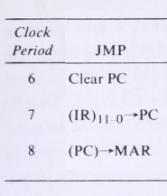
void do_JMP(uint8_t tick)
{
	if (tick == 6) {
		PC = 0;
	} else if (tick == 7) {
		PC = (IR & 0x0FFF);
	} else if (tick == 8) {
		MAR = PC;
	}
}
This is a fun instruction that will let us jump around the code, allowing us to create all sorts of loops in our code. Now, let’s add it to our process_tick routine.
void process_tick(uint8_t tick)
{
    ...
	uint8_t INS = get_instruction();
	if (INS == 15) {
		do_NOP(tick);
	}
	else if (INS == 10) {
		do_JMP(tick);
	}
}
And finally, we change our program to include some jump instructions, compile and run the emulator!
// Sample program
uint16_t program0[6] = {
	0xF000, // Instruction #0
	0xF003,
	0xA004, // Jump to instruction #4 (fifth one)
	0xF005, // This shouldn't be executed
	0xF010,
	0xA000 // Jump back to instruction #0
};
This program should skip 0xF005 and jump into 0xF010, then jump back to the beginning looping infinitely. Let’s verify it works with our debug information.
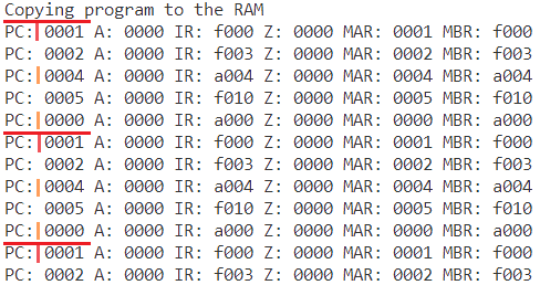
Finally some tasty instructions! As you can see, we’re jumping twice, the first jump will skip instruction 0xF005, then the second jump loops us back to the first instruction 0xF000.
The end result for this part should look something like this
To be continued…
Extending the emulator and adding more instructions will start making our program harder to debug and modify. In the next part of this tutorial we’ll go through the process of adding more instructions to our emulator and making things a little bit more maintainable. We’ll also eventually reach the part where we need to handle IO data, and there are a ton of ways to tackle this topic.
Take a look at the finished emulator or continue fleshing out your emulator in any way you want. You could even define new instruction sets, create a pipeline, change the RAM size, etc. Sky is the limit!