Developing a computer inside an FPGA
A little more than a year ago I started working (on and off) on a new project to improve my understanding of computer architecture and VHDL programming. I've not always been interested in using FPGAs and unfortunately, at university I didn't quite grasp the purpose of FPGA programming.
As I started learning more about low level programming and videogames, I came up with the idea of developing an emulator for the NES inside an FPGA to play on the "original" hardware withouth having to find and maintain one. However, my computer architecture and VHDL skills at the time were almost non-existent, so I decided to start with a simpler project.
After searching for projects, I came across this article from Al Williams on Hackaday. Al suggested starting with a basic computer (BLUE), one that Caxton C. Foster specified in his book "Computer Architecture". I was unable to find this book physically at an affordable price, but eventually I found a borrowable version on archive.org, I love this site!
I created this repository and started translating the simplest parts of the logic gate diagrams to VHDL programs. Sites like nandland.com and vhdlwhiz.com have been especially helpful in teaching me the basics of VHDL development and getting me ready to write this project.
Reinventing the wheel
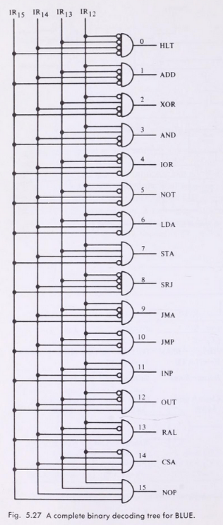
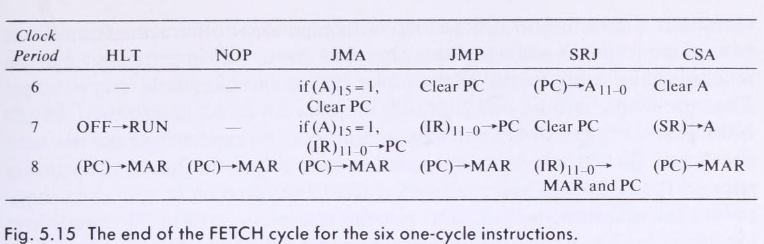
The first thing I did was read through the specification and writing down notes on how the computer really works. There are a lot of nice diagramas and tables which I copied into the repositories README file to keep the important stuff accessible and organized.
Some relevant info about BLUE
- 4096 words of addressed core storage of 16 bits per word.
- Words in data storage as treated as 15-bit integers plus sign.
- Instructions are 4 bit OP code with 12 bit address (4096).
- 16-bit Acc.
- 16-bit instruction register.
- 12-bit program counter.
- 12-bit Memory Address Register, 16-bit Memory Buffer Register and a 16-bit Z register that are not accessible to the programmer.
- 16 different instructions for the 4-bit OPCode.
- If the highest bit is 1, the number is negative.
As you can see BLUE is a really simple computer, perfect for beginners in computer architecture. To be honest, I wasn't expecting things inside a computer to be as simple as they are, with a bunch of logic diagrams, we're able to build complex units that handle rather abstact tasks like arithmetic operations.
At this point, my motivation peaked and I started to get a lot of "aha!" moments, I thought everything was sorted out for me inside these logic diagrams and I was ready to jump into the code and start programming.
Morning stiffness
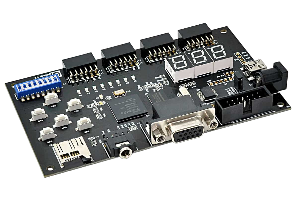
As always, setting up the tools and stuff you need to actually do the coding can be really tedious. For this project I ordered an FPGA from Numato, specifically, the MimasV2. It comes with a nice board full of IO components to test your designs and has worked really well so far. I can't tell yet if this board is enough to support a full NES emulator though. One of the struggles I faced was setting up the software I needed to write the code, flash the FPGA and also sort out how things worked overall. It had been a while since I last used Xilinx ISE, and I had never used it before on a Linux machine.
Once I got ISE ready to go, I tried to figure out how to actually flash the FPGA with the binary file that is generated from the VHDL code. At first I tried to run a Python utility "provided" by Numato to flash their devices, but I just couldn't get it running. The best tool to flash the FPGA runs only on Windows, so after giving up on the Linux tool I decided to try and run the Windows tool using Wine, it worked like a charm.
After doing a few beginner level FPGA projects, I felt ready to jump into programming a clock module for BLUE.
Working as a translator
While I was programming the clock module, I started to notice things wouldn't be as straightforward as copying all the logic gate diagrams to VHDL statements, or at least, that wouldn't be the easiest way to do it. I wanted to have a middleground between copying exactly the diagrams I found and simplifying things to better fit with VHDL statements.
From what I can gather, the clock module of BLUE is a bit unconventional, even the author suggests doing things in a different way. The important stuff is that a cycle in BLUE is made of 8 clock steps, there's a signal for each step which will be used to define what needs to be done for each instruction.
The clock for BLUE in VHDL is basically a process loop that at a set minor frequency (50 MHz) rotates a bit on the clock steps signal. You could think of it as a semaphore with 8 lights that takes 0.16 micro seconds to go through all the lights, that's fast!
I wanted to start with the simpler instructions for this project, so the first step was coding all the necessary stuff to get the NOP, HALT, and JUMP instructions ready.
As soon as I finished programming registers like the Memory Buffer Register, Memory Address Register and Program Counter, I began programming what I call the Control Unit, although I'm not entirely sure if this is the right term. The Control Unit would be the part that orchestrates the interactions between all the registers, instructions and power options. Currently in my code this part of BLUE is a mess, there are too many lines of code for my test and I'm sure there's a way to isolate things a little better, especially the instructions decoding part.
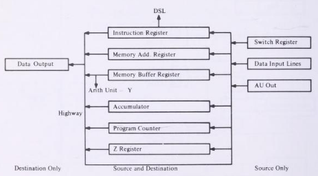
When I began programming the CU, I noticed I wouldn't be able to actually program a Bus that connects between several registers as described in the book, at least not with my current skill level. I searched around the web on how to program such thing, but a lot of people seemed to advice towards using multiplexing instead of actually programming buses, so I followed this advice.
Not quite there yet
After a lot of struggle and almost 45 hours of free time later, I had this basic "computer" that could interpret NOP, HALT, and JUMP instructions! It ain't much, but it's honest work.
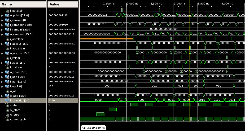
Currently, my BLUE implementation is also able to process store/load and arithmetic instructions, I started coding the ALU and two different states for double cycle instructions like ADD. I've learned a lot about VHDL along the way and I wish to finish coding BLUE, however, there are some challenges I need to tackle first. As I start adding more instructions, debugging becomes more and more complicated, those signal diagrams from the simulations are a bit confusing and I wonder what other ways exist to debug the whole thing.
In order to ease things in the future, I plan on adding a debugging feature to dump the content of the RAM and each individual register via serial communication, and then arrange that data in some sort of user interface. This should help me debug programs and the actual behavior of the computer. Additionally I'm also working on writing a C++ software emulator, which I'll describe in a later post, which is surprisingly easier to implement than the actual VHDL thing.
Feel free to use the project's repository as you wish, this is a learning exercise I really recommend doing to anyone interested in basic computer architecture and FPGAs. I'm still far away from my actual goal of coding a hardware emulator for the NES, but it's been a really fun project to do so far and hopefully I'll be able to finish it soon. Also I started taking this course by the LinuxFoundationX that teaches how to program a RISC V processor, haven't finished it yet, but it seems to be a good way to start with computer architecture: https://www.edx.org/course/building-a-risc-v-cpu-core