Using an RGB display with embedded C
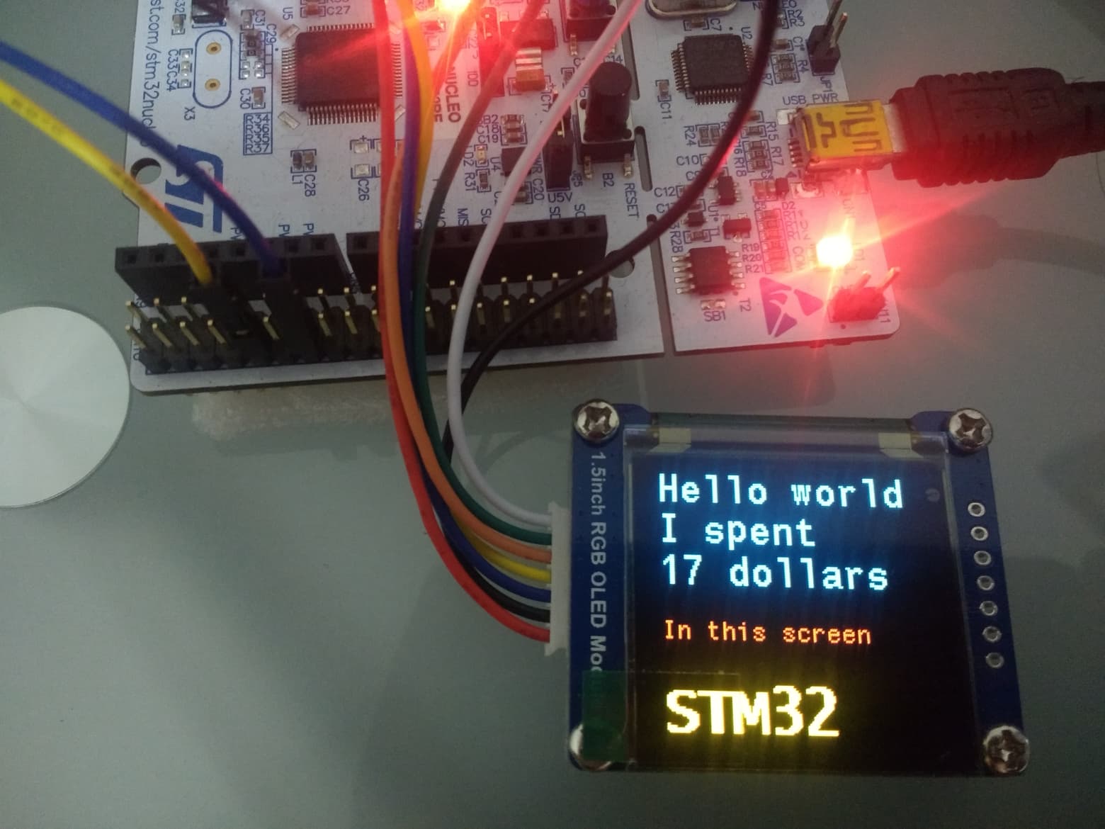
Two months ago I got a new 128x128 OLED Display to play with, this time it was the SSD1351. This OLED display, although limited, supports RGB colors which has been very exciting as it’s my first time working with one of those. I got this display from ebay for around $17, a relatively cheap price if we consider its potential.
For this display I decided to create my own driver library, inspired by the library I used for the SSD1306 in the previous entry, with subtle support for printing and graphics display, like rectangles, circles and lines.
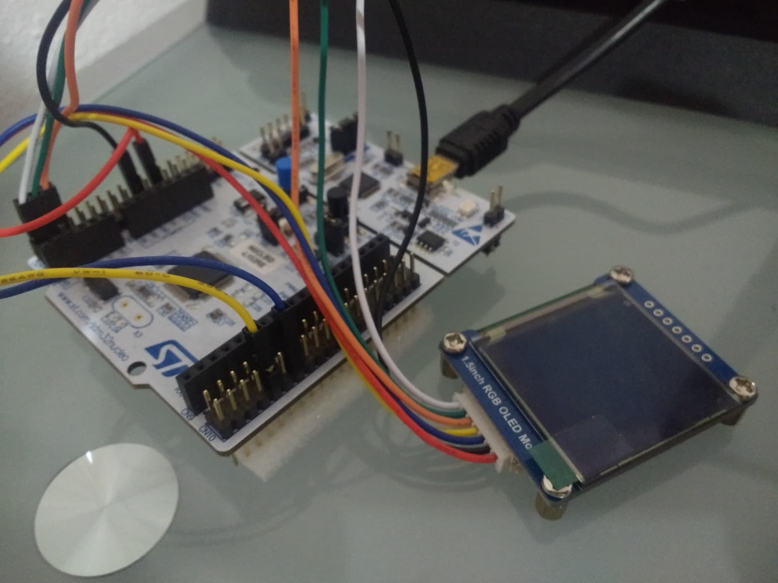
I’ll describe the basics of the development for this library for everyone curious about rudimentary graphics programming. I’m also using the same development board as before, the Nucleo L152RE and SW4STM32 as the IDE, however, this library was adjusted to be of generic use in C regardless of the hardware you’re using. Some configuration is needed inside the ssd1351.h header file though.
Relevant hardware information
As a low level programmer it’s important to look for the data-sheet and specifications of the devices we’re is programming for. So for prototyping, the relevant information we can get from the data-sheet is the following:
- SPI communication(3 or 4 wire)
- 2.4V – 3.5V Power supply
- 128x128x18 SRAM Display Buffer (more on this later)
- 262k color depth
- Data/Command Pin
Start your engines
Personally speaking, initialization process is the toughest stage of the development of a driver library, especially if it’s the first time you’re working with the hardware. There’s a lot of information you need to extract from the data-sheet like configuration options, communication modes, working modes, timings, and initialization routines. It’s also the time to create your long list of command and constant definitions, hardware abstraction layer definitions, and more. On top of that, add the excitement of wanting to get your device running as soon as possible and see all that magical stuff you can do with it.
Once the display turns on and it’s ready to receive data, it’s necessary to unlock the majority of the commands via a special command, then we’re ready to send all the configuration stuff we want to change from the original reset values.
Communication is key
The way to tell the display what to do is based on commands and data transmission. For 3-Wire SPI we only need CS, MOSI and MISO pins as well as an extra pin called C/D to tell the display whether we’re sending a data byte or a command byte. To send a command, the C/D needs to be in logical low and to send data it needs to be in logical high.
Some commands are followed by one or more bytes of data, and some of them are not, everything is described on the data-sheet. For example, to send the starting and ending row numbers as 0 and 127, we first send the 75h command byte followed by 00h and 7Fh data bytes. Inside the library, the communication has been abstracted under three “wrapper” functions that every user needs to link to their own HAL. One function is designed to send a command byte, another one to send a data byte and a third one to send a buffer of a specified length.
The display RAM
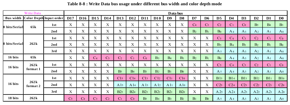
The display RAM is the most interesting part of the display because it’s where the fun happens. This RAM works as a long array of bytes where each pixel has a total of 18 bits to store the intensity of each color(red, green and blue), so each color is represented by a value of 6 bits. Now, 18 bits is kind of a large number to handle, so to make things easier both in storage and communication, the display offers a variety of color modes. Each color mode has a specified data length to work with, the lower the length the less colors we can use.
The best approach to make changes in the display is to perform all the color changes in a local RAM array inside the MCU and, when we’re ready, send the “Write RAM” command followed by all the bytes we’re using to change each pixel’s color. This way we avoid excessive and unnecessary writing to the SPI port which also reduces the time needed to perform complex drawings onto the screen.
For the library I decided to use the lowest color depth available as it matches quite well the 8-bit SPI communication and it makes byte handling easier. This means we only have to use 5, 6 and 5 bytes for reed, green and blue colors respectively, adding to a total of 2 bytes per pixel. There’s already a function to perform the conversion from rgb values to a single integer of 16 bits.
Psychedelic stuff
With all these tools, we can start writing the fun graphics stuff that involves all the algorithms to draw lines, polygons, circles, and character printing. I gotta admit that other than the rectangles, I didn’t come to these algorithms by my own, there are already optimized algorithms to draw pixelated lines and circles. Currently there are functions to draw individual pixels, draw lines, rectangles, filled rectangles, circles, filled circles, and character printing.
The character printing stuff is heavily based on Olivier van Ede’s “ssd1306-stm32HAL”, which is a library for a mono-chromatic OLED display that I used on my previous project. Basically all the fonts files stayed the same except for a few adjustments in readability and generic usage. The formatted printing is a limited feature, it only supports three data types: strings, characters and signed 8-bit integers, as well as the escape character ‘\n’.
Building upon
The next step is going back to the Breakout-like game and develop a way to load sprites from a file system. Then maybe even extending to a graphics library to something more sophisticated as well as importing Lua scripts into a STM32 microcontroller to make simple games that use this library. You can find three demos listed in the main readme file of the repository. As always, if you’re curious then feel free to fork and test this library into your own favorite micro-controller. Repository here